The last chapter of the tutorial has a forward-renderer system, where we calculate lighting on the pixel shader of the object draws, and output to the renderer image. But for the Ascendant project, a lot more features are required. Volumetrics, SSAO, tonemapper, dynamic lighting, shadows. For this reason, the renderer was moved to a deferred system. The voxels and meshes drawn will write into a GBuffer, and then it applies all of the lighting features as compute passes on top of that. This required a big reorganization, and a system to keep track of all the required syncronization over the rendering images and intermediate targets.
Synchronization
In the tutorial, barriers are done as a call like ` vkutil::transition_image(cmd, new_image.image, VK_IMAGE_LAYOUT_UNDEFINED, VK_IMAGE_LAYOUT_TRANSFER_DST_OPTIMAL);` . This directly encodes the barrier command. This was fine with the tutorial, as its sync needs werent much. But now that we need to deal with gbuffers and indirect command buffers, we often see cases like encoding 8 barriers at a time into the commands. The GPU driver doesnt really like to handle barriers like this, and it performs better if it does a single VkCmdPipelineBarrier that does multiple barriers at a time, instead of multiple vkCmdPipelineBarrier calls.
To fix this, ive implemented a BarrierMerger utility class, which mantains the logic of the “instant” vkutil calls, but just batches all into a single VkCmdPipelineBarrier call.
struct BarrierMerger {
    eastl::fixed_vector<VkImageMemoryBarrier2, 10> imageBarriers;
    eastl::fixed_vector<VkBufferMemoryBarrier2, 10> bufferBarriers;

    void transition_image(VkImage image, VkImageLayout currentLayout, VkImageLayout newLayout, ImageBarrierPresets preset = ImageBarrierPresets::Gigabarrier, VkImageAspectFlags aspectMask = VK_IMAGE_ASPECT_COLOR_BIT);
    void transition_image_mipmapped(VkImage image, VkImageLayout currentLayout, VkImageLayout newLayout, int startMip, int endMip, ImageBarrierPresets preset = ImageBarrierPresets::Gigabarrier, VkImageAspectFlags aspectMask = VK_IMAGE_ASPECT_COLOR_BIT);

    void buffer_barrier(VkBuffer buffer, BufferBarrierPresets preset = BufferBarrierPresets::Gigabarrier);

    //actually calls the VkCmdPipelineBarrier with all the barriers on this and clears
    void flushBarriers(VkCommandBuffer cmd);
};
The barriers across the frame were all modified to use this to improve performance a bit. The mechanics of transition_image and other calls are the same as seen in the tutorial.
RenderGraph
While the barrier merger is handy, its still completely manual. And when one is developing a engine that has many compute and draw passes for various things, keeping track of all the barriers needed for everything gets out of hand very quickly. On the tutorial it wasnt a problem because we only had 3-4 steps, but even at that scale the barriers were already annoying and a common source of mistakes. To automate the barriers across render passes, i implemented the RenderPass system. This is a very simplified version of the framegraphs you see in AAA engines. For a look into a really good talk about that, you can check here Frostbite Framegraph. The design here is a highly simplified version of a similar concept.
Here is the api of the system. It has a Rendergraph::Builder which is the core of the system.
namespace RenderGraph {
    struct Builder {
        void AddComputePass(const char* name, eastl::function<void(Pass&)> setup, eastl::function<void(PassExecution&)> run);

        void AddGraphicsPass(const char* name, eastl::function<void(Pass&)> setup, eastl::function<void(PassExecution&)> run);

        void AddTrackedImage(const char* name, VkImageLayout startLayout, AllocatedImage* image);
        void AddTrackedBuffer(const char* name, AllocatedBuffer* buffer);

        void Build();
        void Run();
    };
}
It has 2 types of passes. The compute pass is for compute shaders, and doesnt perform any logic in regards to starting or stopping a vulkan dynamic rendering renderpass. The graphics pass does start/stop renderpasses.
This builder is created from scratch every frame, which allows for simple toggling of features on and off and everything will keep working. When creating it, the first thing is to call the AddTrackedImage/Buffer functions, which inserts a image or a buffer into the tracking system.
The pass functions have 2 lambdas. One is for setup, and its called immediately when building the graph. The other lambda is called when actually executing the graph. The idea is that the setup lambda is used for declaring what images and buffers does each pass read/write, and then the execution lambda runs the real commands. For example, here is how the SSAO pass looks.
if (CVAR_SSAOMode.Get() == 1 && SSAOpostFX) {
    rdg.AddComputePass("fidelity FX SSAO",
        [](RenderGraph::Pass& pass) {
            pass.ReadsImage("gbuf:normal", VK_IMAGE_LAYOUT_SHADER_READ_ONLY_OPTIMAL);
            pass.ReadsImage("depth", VK_IMAGE_LAYOUT_SHADER_READ_ONLY_OPTIMAL);
            pass.ReadsImage("ssao", VK_IMAGE_LAYOUT_SHADER_READ_ONLY_OPTIMAL);

            pass.WritesImage("ssao");
        },
        [&](RenderGraph::PassExecution& exec) {
            SSAOpostFX->RunSSAO(exec.encoder->cmd, _depthImage, _gbufNormal, _SSAO);
        }
    );
}
else {
    rdg.AddGraphicsPass("ssao stub",
        [](RenderGraph::Pass& pass) {
            static VkClearValue clear;
            clear.color.float32[0] = 1;
            pass.AddColorAttachment("ssao", true, &clear);
        },
        [&](RenderGraph::PassExecution& exec) {
            //nothing
        }
    );
}
If SSAO is enabled on the CVAR settings, it performs a compute shader pass where it reads gbuffer normal and depth, and writes a SSAO texture. Then calls into the FidelityFX library to actually run the proper compute passes from the execution lambda. If SSAO is not enabled, it runs a stub graphs pass where it just does a image clear on the ssao texture that the lighting calculations use.
Note that the ssao image has both read and write calls on the setup lambda. This is because the ReadsImage will guarantee the image is at a given layout, which is then used for barriers in the fidelityFX library.
The rendergraph does NOT perform any sorting or scheduling logic. Its going to run the passes linearly. What its automating is the barrier logic. After the setup lambdas are called for all the passes, we have a list of Pass structures which contains the image information for the layouts, color attachments, and other required information.
Buffers dont have as many options as images, as for those its doing a full memory barrier.
struct Pass {
    //assumes compute style
    void ReadsImage(const char* name, VkImageLayout layout);
    void WritesImage(const char* name);

    //attachments
    void AddColorAttachment(const char* name, bool store, VkClearValue* clear);
    void AddDepthStencilAttachment(const char* name, bool store, VkClearValue* clear);

    void CreatesBuffer(const char* name, size_t size, VkBufferUsageFlags usages);

    void ReadsBuffer(const char* name);
    void WritesBuffer(const char* name);

    PassType type;

    eastl::vector<PassImageRead> imageReads;
    eastl::vector<PassImageWrite> imageWrites;

    eastl::vector<PassImageRead> colorAttachments;

    eastl::vector<PassBufferCreationInfo> bufferCreations;
    eastl::vector<const char*> bufferDependencies;

    Nametag name;
    PassImageRead depthAttachment{};
    bool storeDepth;

    Builder* creator;
};
## Executing the RenderGraph Once this list of passes is generated, it needs to execute them in order. When the rendergraph execution begins, the first thing it does is to go through all images, and pre-barrier the first usage of each image. This way we are batching things a bit. After that, it executes each pass at a time. On each pass, it checks what image layouts and barriers the pass wants, and adds the barriers to the BarrierMerger seen above. This uses the read + write information seen on the pass. It then does a barrier flush to perform the barrier, and calls the execution lambda so that the vulkan commands are executed. After the pass is executed, the information from the imageWrites to set some flags on those resources, which the next pass that uses them will keep in mind when calculating the needed barriers for the pass.
This system is going to be doing 1 barrier for most passes. More advanced rendergraph systems will reorder passes or calculate the barriers more accurately to try to “merge” passes without barriers between them. For this engine, i made sure that the passes are defined in a way that they dont share image reads/writes, which allows the system to skip barriers between passes in various points.
## Deferred rendering

The frame begins by rendering the meshes and voxels into a series of gbuffer images. The ones used are Color ( RGBA 16), Normal (RGBA8), and Depth (D32) I dont have roughness, metallic, or anything of the sort as there was no need. By limiting the number of gbuffer images, it improves performance. The Depth is used for depth testing, but its also used later on the frame for more things.
After rendering the main view, it also does the shadow passes, which render cascaded shadows.
After writing the gbuffer, it runs a SSAO pass. This reads from the depth image, and outputs a ssao image that is used later when calculating lighting. This SSAO could be run in async compute with the shadow passes, but i didnt see much of a performance win by doing that, so at the end i didnt do it. Its really common on game engines to overlap SSAO calculations with shadow passes, but it being a perf win or not highly depends on what those two are doing.
Next, it runs a compute pass that writes the sun shadow information into another render target image. This uses a compute shader, and reads from the depth image and the cascaded shadow maps, uses depth to reconstruct world position, and ends up with a black and white shadow image from the sun. I also do contact shadows here, where it accesses the depth pixels in a line in the direction of the sun, and applies a bit of a extra shadow blended with the real one. This improves look at far distances, where the cascaded shadows have ended their range.
Here is the result of the sun shadow pass. 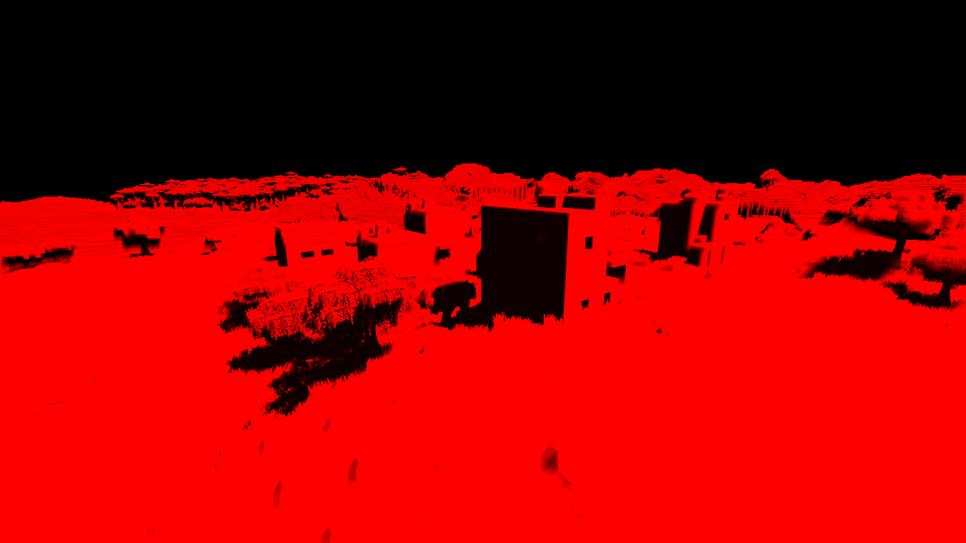
Then the engine calculates sky. This is done through atmospheric volumetrics, taken from A Scalable and Production Ready Sky and Atmosphere Rendering . This system calculates atmospheric scattering for a realistic sky and far distance fog. The implementation is partial, i only implement the bare minimum of it, not all of its features. The cost is very low. The “far distance” sky is applied with a compute shader on the draw image, as background where depth is 0.
It not only has the sky atmosphere, but also other volumetrics. These are based on the frostbite paper here. Unreal engine uses a similar volumetric system. The way it works is that it creates a frustum aligned 3d grid, and calculates the fog illumination per voxel. then it builds a lookup 3d texture where it raymarches through this + it gets temporally accumulated with the last frame. Im applying the sun cascade light into this, which gives fancy sun shafts, and also hook terrain height into it. This gives a nice foggy system i can tweak per biome and others.
Unlike the sky, the volumetrics are quite expensive. The 3d volume needed ends up using a fair amount of compute, so it can take up to 1 milisecond on the steam deck. Higher if i increase its resolution.
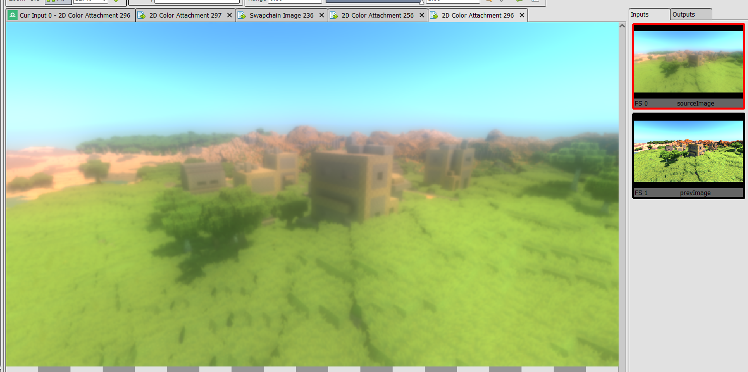
With all those things calculated, its time to apply them to the image. The first pass is a GbufferApply pass, which calculates the full lighting. This pass loads the color and normal from the gbuffer, and calculates the whole lighting necessary for the image.
Using the SSAO for blending, it applies “ambient” lighting. By using the ssao to mask it, it keeps the corners darker. The ambient light is calculated by using the atmosphere system to create a cubemap, and downsampling it to find a ambient light parameter that includes the blue sky (if at day) plus a green ground color (the color can change depending on what biome you are at. its an approximation)
With the sun mask image, it gives the pixels where it needs to add the lighting from the sun. Using the sun mask image skips having to calculate shadow logic on this pass as we already did it before.
Then, it applies the point lights. These are culled and uploaded to the GPU from the cpu every frame, and are applied in a completely bruteforce fashion. In this project you dont see that many point lights, so for something on the “dozens” scale, such a bruteforce way works completely fine. If the project had more lights, then it would need to use some acceleration structure to avoid calculating every light on every pixel, for example a tiled lighting system where it divides the screen into square tiles, and loops the lights on each tile only.
[loop]
for (int i = 0; i < pushConst.pointLightCount; i++) {

    GPUlightParameters light = pushConst.PointLights[i];

    //distance squared check as a fast-path
    float distSQ = dot(pixelWorldPosition.xyz - light.lightPosition, pixelWorldPosition.xyz - light.lightPosition);
    bool inRange = distSQ < (light.attenuationRadius * light.attenuationRadius);

    //by using wave-operations it improves the performance a bit of this branch. Tested
    if (WaveActiveAnyTrue(inRange)) {
        finalColor += evaluatePunctualLightPBR(V, N, pixelWorldPosition.xyz, albedo, metallic, roughness, light);
    }
}
The result of applying the gbuffer gives this. 
We have the image with all the materials rendered and their lighting, but we are missing a few things still.
Next, it applies fogging effects, by grabbing the 3d volume from the volumetric pass, and the information from the atmospheric pass, and applying them as a tint on top of the image.
After the main fogging, the transparent objects are drawn, and they also calculate fog in their pixel shader, which allows them to blend into the image in a plausible way.
With the fogged image with transparents, now the engine performs a series of downsample and upscales on the image, to perform a large scale blur. This blur is then used to implement bloom.
The implementation i use is from here Custom Bloom Post-Process in Unreal Engine . Note that this is an article where it replaces the unreal engine bloom with this one, but i copy the technique and shaders to vulkan for Ascendant. It performs well and looks great.
This bloom blur is combined into the image on the tonemapper pass, which also copies the image into the swapchain, and performs optional FXAA antialiasing. Tonemapping makes the image go from the current f16 format we are accumulating light in, to the final “for the screen” image, making sure to apply exposure and change the linear lighting colors to a more logical tone.
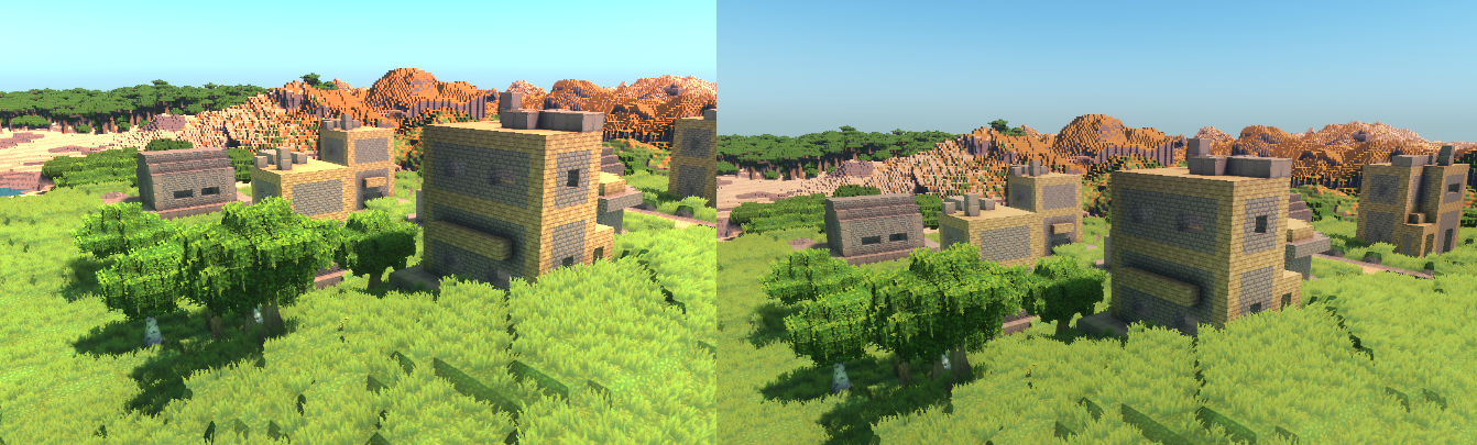 On the left, you can see the image without tonemapping, as seen on renderdoc. On the right, you see the effects of the tonemapper, which has fixed the blown out highlights in the sky and buildings.
All that is left is the UI rendering, which is done through imgui.