Push Constants
We can render arbitrary meshes now, but there is not a lot we can do with them. We still don’t know how to send data from the CPU to shaders outside of vertex buffers. While the next chapter will explain the various methods in detail, there is a simple method we can start using immediately: push constants.
Push constants let us send a small amount of data (it has a limited size) to the shader, in a very simple and performant way. Push constants can send data to any shader stage (both vertex and fragment shaders), and are stored in the command buffer itself.
To use push constants, you first need to set their size (in each stage) when you create a VkPipelineLayout. Then, using the command vkCmdPushConstants, the data will be embedded into the command buffer, and will be accessible from the shader. We are going to use them for transformation matrices, to be able to move objects around and do proper 3d rendering. To start, we are going to use it to move the triangle we are rendering.
New PipelineLayout
We are going to need a new PipelineLayout to hold the push constant sizes. For that, we are going to add a new member to vulkanEngine.
class VulkanEngine {
public:
	///other code...
	VkPipelineLayout _meshPipelineLayout;
	//other code ...

}
We are also going to create a struct to hold it in vk_engine.h
//add the include for glm to get matrices
#include <glm/glm.hpp>

struct MeshPushConstants {
	glm::vec4 data;
	glm::mat4 render_matrix;
};
For now, we will just store a single glm::vec4 into it (4 floats) and a glm::mat4 (16 floats). We will then use the matrix to transform the triangle. When you create push constant structs, alignment rules apply. You can find the exact rules for them by reading about the GLSL std430 layout. These can be very complicated, so for simplicity, we are going to restrict ourselves to glm::vec4 and glm::mat4, which have simple alignment rules. Push constants have a minimum size of 128 bytes, which is enough for common things like a 4x4 matrix and a few extra parameters.
To make space for the push constants in the pipeline, we create it inside the init_pipelines() function
	//we start from just the default empty pipeline layout info
	VkPipelineLayoutCreateInfo mesh_pipeline_layout_info = vkinit::pipeline_layout_create_info();

	//setup push constants
	VkPushConstantRange push_constant;
	//this push constant range starts at the beginning
	push_constant.offset = 0;
	//this push constant range takes up the size of a MeshPushConstants struct
	push_constant.size = sizeof(MeshPushConstants);
	//this push constant range is accessible only in the vertex shader
	push_constant.stageFlags = VK_SHADER_STAGE_VERTEX_BIT;

	mesh_pipeline_layout_info.pPushConstantRanges = &push_constant;
	mesh_pipeline_layout_info.pushConstantRangeCount = 1;

	VK_CHECK(vkCreatePipelineLayout(_device, &mesh_pipeline_layout_info, nullptr, &_meshPipelineLayout));

	//later ....
	//remember to destroy the pipeline layout
	_mainDeletionQueue.push_function([=]() {
        	//other deletions

		vkDestroyPipelineLayout(_device, _meshPipelineLayout, nullptr);
	});
Push constants are written in ranges. A important reason for that, is that you can have different push constants, at different ranges, in different stages. For example, you can reserve 64 bytes (1 glm::mat4) size on the vertex shader, and then start the pixel shader push constant from offset 64. This way you would have different push constants on different stages. Given that getting the ranges right is tricky, in this tutorial we are going to use a more monolithic approach of using the same push constants on both vertex and fragment shader.
Now that we have the layout, we also need to modify the shaders. Let’s add the push constant to the tri_mesh.vert shader.
#version 450

layout (location = 0) in vec3 vPosition;
layout (location = 1) in vec3 vNormal;
layout (location = 2) in vec3 vColor;

layout (location = 0) out vec3 outColor;

//push constants block
layout( push_constant ) uniform constants
{
	vec4 data;
	mat4 render_matrix;
} PushConstants;

void main()
{
	gl_Position = PushConstants.render_matrix * vec4(vPosition, 1.0f);
	outColor = vColor;
}
The push_constant block has to match to the struct we have on C++ side 1 to 1, otherwise the GPU will read our data incorrectly.
Now we can modify the way we create the triangle pipeline to hook the new pipeline layout.
in init_pipelines, right before creating the mesh pipeline, we are going to hook the new layout
    pipelineBuilder._pipelineLayout = _meshPipelineLayout;

    _meshPipeline = pipelineBuilder.build_pipeline(_device, _renderPass);
Now our mesh pipeline has the space for the push constants, so we can now execute the command to use them.
in draw() function, right before the vkCmdDraw call, we are going to compute and write the push constant.
    //make a model view matrix for rendering the object
    //camera position
    glm::vec3 camPos = { 0.f,0.f,-2.f };

    glm::mat4 view = glm::translate(glm::mat4(1.f), camPos);
    //camera projection
    glm::mat4 projection = glm::perspective(glm::radians(70.f), 1700.f / 900.f, 0.1f, 200.0f);
    projection[1][1] *= -1;
    //model rotation
    glm::mat4 model = glm::rotate(glm::mat4{ 1.0f }, glm::radians(_frameNumber * 0.4f), glm::vec3(0, 1, 0));

    //calculate final mesh matrix
    glm::mat4 mesh_matrix = projection * view * model;

    MeshPushConstants constants;
    constants.render_matrix = mesh_matrix;

    //upload the matrix to the GPU via push constants
    vkCmdPushConstants(cmd, _meshPipelineLayout, VK_SHADER_STAGE_VERTEX_BIT, 0, sizeof(MeshPushConstants), &constants);

    //we can now draw
    vkCmdDraw(cmd, _triangleMesh._vertices.size(), 1, 0, 0);
You will also need to add
#include <glm/gtx/transform.hpp>
To the vk_engine.cpp file so that you can use the glm transformation matrix functions.
In the push constant call, we need to set the pointer to the data and its size (similar to memcpy), and also VK_PIPELINE_STAGE_VERTEX_BIT, which matches the stage(s) where our data should be accessible. If we have the same push constant on both vertex and fragment shader, we would have both of those flags.
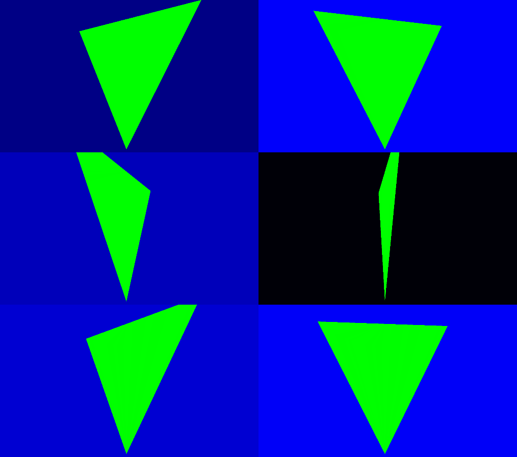
If you now run the program, you will see the triangle spinning in the window, upside down. By modifying camPos and the view matrix in general, you can now create a 3d camera.

Next: Loading OBJ Meshes